The Supermarine Spitfire is undoubtedly one of the most iconic aircraft ever to have flown. Despite this, technology has advanced and parts of the aircraft have become obsolete and are no longer made.
This month, X-ray Applications Engineer James Finch had the privilege to assist the RAF 71(IR) Squadron by scanning the top fuel tank of an Mk19 Spitfire. With no reliable part number-specific drawings available, the scan was to ascertain the ability to manufacture a replacement should one be required.

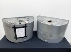
Figure 1: Fuel tanks loaned to us by RAF 71(IR) Squadron for the purpose of reverse engineering. Each tank is ~830x460x520mm.
The X-ray CT data was acquired at a voxel resolution of 210μm using 160kV, a power of 330W, and used a combination of 2×2 detector binning for both speed of acquisition and to limit the size of the data. This was a 3-position panel scan in a Nikon Large Envelope System (C2), which houses a Nikon 225kV and 450kV rotating micro-focus targets, as well as a Varian HPX-450kV mini-focus target; paired with a Varex 4343N flat panel detector.
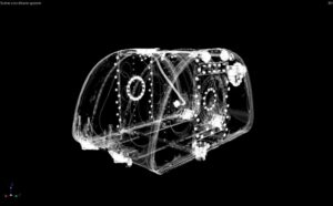
Figure 2: 3D render of the fuel tank, using VGSTUDIO MAX 2022.1
To scan the tank in its entirety, five of these acquisitions were performed, merged and then calibrated using a ruby sphere pair to provide even more accurate dimensions to the data. Each scan consisted of 19,272 projections at an exposure of 177ms, averaging at four frames per projection – leading to a total scan time of 19 hours for the whole tank. While the data could have been acquired in a quarter of the time (by not averaging frames), data quality was prioritized due to the unique origin of the part.
Figure 3: 2D slices from the rear of the tank to the front (as seen in Figure 1).
While scanning the part, we became curious as to how the fuel level was detected and/or controlled. Therefore, we decided to perform two ‘Region of Interest’ scans. The first was on the fuel-level mechanism, which appears to function by way of a float (not in the ROI data) that raises and lowers with the fuel, which feeds back via turning a central axis and electrical contacts:
Figure 4: 2D slices through the fuel-level mechanism. The cabling protrudes from the front of the tank (as seen in Figure 1).
The second was on the overflow-limiter, which again appears to operate by way of another float, except when the level is too high a piston is floated into place to stop any more fuel from entering the tank:
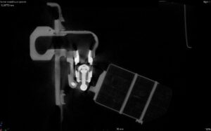
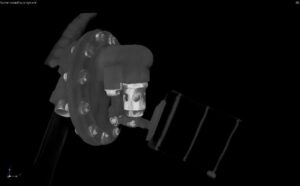
Figure 5: 2D slice, and 3D render of the overflow-limiter mechanism in VGSTUDIO MAX 2022.1
In conclusion, X-ray CT enables us to non-destructively visualize the different components of the fuel tank, as well as to understand its mechanism.


