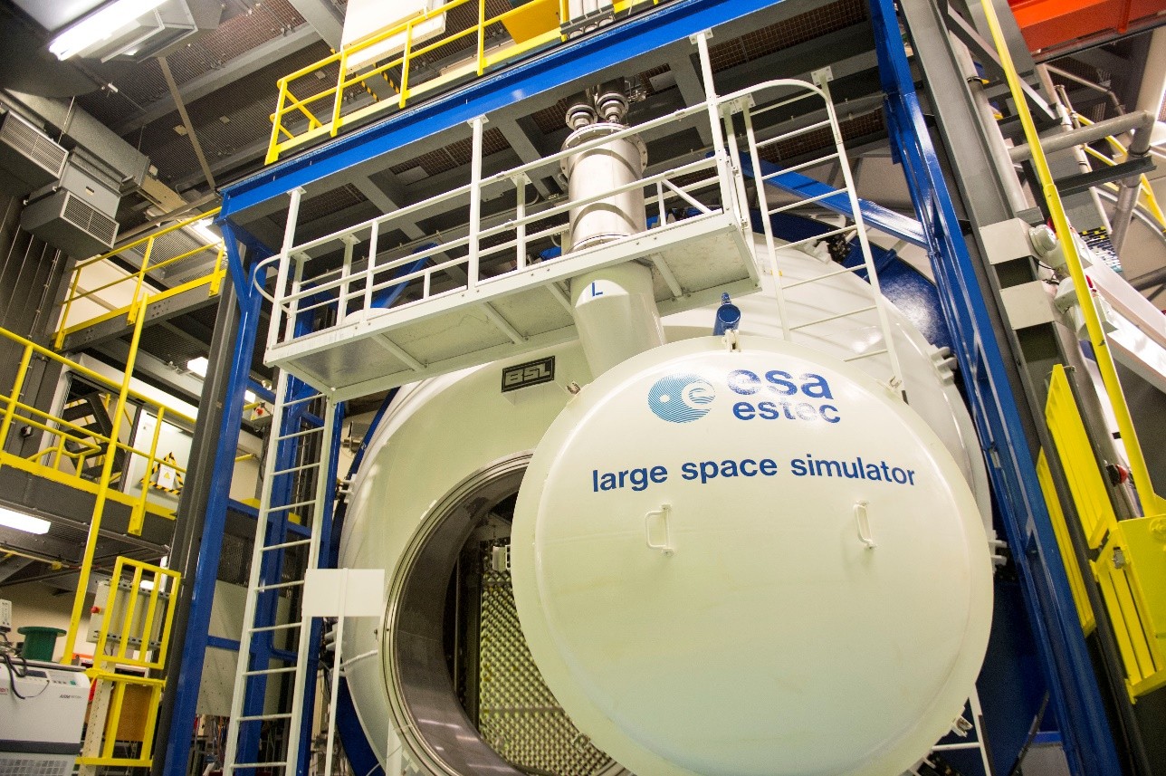
In a groundbreaking development at ESTEC (European Space Research and Technology Centre), the largest testing facility for spacecraft of the European Space Agency (ESA), a Laser Radar system supplied by the Industrial Solutions Business Unit of Nikon Corporation (www.industry.nikon.com) is taking the precision and speed of some pre-launch assessment tasks to the next level. The innovative technology, being implemented by an ESA team, based in Noordwijk, the Netherlands, headed by ESA metrology engineer Steven Sablerolle, is set to revolutionise the way spacecraft are prepared for their missions.
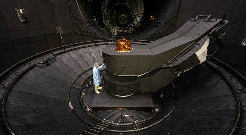
Before a satellite is sent into space, it undergoes rigorous testing in a large space simulator to ensure its functionality and durability in the harsh conditions of the cosmos. The simulator, which is 10 metres in diameter and 12 metres high spread over four floors, comprises two chambers held at a vacuum of one ten-millionth of a millibar and a temperature of minus 180 degrees Celsius. In the main section, a satellite or other test item is mounted on a 5-axis motion control apparatus so that its spatial position can be adjusted. The auxiliary chamber accommodates a collimation mirror designed to project the sun’s rays into the main chamber on the spacecraft and it was in this area that the Laser Radar delivered a stunning improvement in metrology.
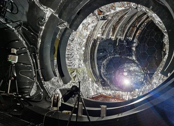
Preparing a spacecraft for launch involves checking vibration, acoustic noise, thermal vacuum and electromagnetic compatibility. A final inspection is performed to see how it will respond to intense radiation from the sun in space. Enabling this test is a seven metre wide collimation mirror, whose 121 hexagonal segments must be accurately positioned and aligned so that the mirror can direct an intense beam of light onto the exterior of the spacecraft to predict how it will be affected by solar irradiance. Formerly, the alignment process was time-consuming, taking three people four weeks to complete. Two operators deployed a pair of laser trackers, a theodolite, a white cinema screen and a camera, while a third person behind the mirror manually adjusted the position of each individual segment by turning three screws. The measurement is made more difficult by not being able to touch the surface of the mirror itself.
In a trial carried in 2024, a Nikon APDIS MV430 Laser Radar system (https://industry.nikon.com/en-gb/products/laser-radar/apdis-mv4x0) mounted on a moveable tripod measured the geometry and position, as well as the curvature, of a single mirror segment to extremely high accuracy. As the Laser Radar can measure even highly reflective surfaces directly with a long range laser beam, to high accuracy, it was ideally suited to this challenging application.
The Laser Radar system for checking the position of the hexagonal mirror segments and aligning them precisely has helped enormously.“ – Steven Sablerolle, ESA metrology engineer
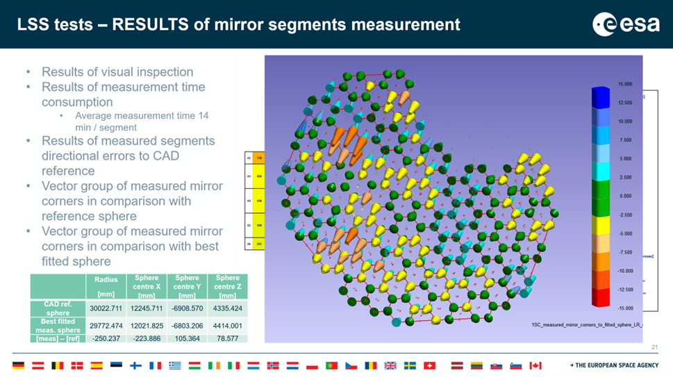
Following this evaluation, a full-scale alignment was performed in July on the complete mirror to test the effectiveness of its light collimation when every segment is orientated to similar accuracy. It only took two people two weeks to complete – one-third of the operator-weeks compared with the previous method. Additionally, the accuracy of the measurements was improved by a factor of 3.6 to 50 arc-seconds, compared with three arc-minutes before. This applied to all six degrees of freedom of a segment, three for position and three for rotation.
Being able to align the segments so precisely means that the mirror array can project a beam with better homogeneity that is able to simulate up to 10 solar constants when it is aimed at a satellite’s housing. It mimics the intensity of the sun in the vicinity of Mercury, whereas previously only 2.4 solar constants was configured, simulating the irradiance experienced by Venus. The improvement is a result of three factors: more accurate knowledge on the projection of the light beam; speeding up the ability to collimate it into a smaller diameter to achieve higher power per unit area; and better homogeneity of the illumination with lower peak-to-valley deviation, which is now less than +/- five percent.
Mr Sablerolle commented, “The Laser Radar system for checking the position of the hexagonal mirror segments and aligning them precisely has helped enormously. It is not feasible to increase the power of the light sources in the basement, so the only way to boost the power of the beam is to re-align the mirror’s orientation, which in turn required the segments to be measured more accurately.”
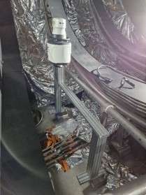
“Our APDIS process is not perfect yet, as we could not position the sensor so that the entire mirror surface could be seen at a seven-metre standoff from outside the chamber, an optimal distance that was required to achieve the accuracy we needed. Only about 80 percent of the mirror was accessible. We are, however, working on a solution that may involve mounting the unit on a mobile temporary structure inside the chamber.“
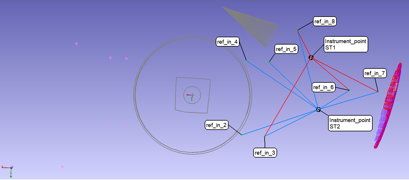
“The support provided by the Laser Radar system sales engineer and a spatial expert from the manufacturer’s reseller in Spain has been exemplary. The engineers spent best part of a week here covering both the theoretical aspects of the measuring technology and practical applications such programming the measurement into an automatic script. They also analysed our specific metrology requirements. By the end, we had decided upon the best locations on the segments for taking measurements, which turned out to be three of the six corners towards the periphery, and had worked out the optimum number of measuring points per scan line.”
The successful implementation of Laser Radar technology for these two projects at ESA represents a significant milestone in the field of space exploration and signals a paradigm improvement in the quality control of test equipment for satellites and also their manufacture.
Scripting was written for automating the alignment process and optimising the measurement of the highly reflective surface of the mirror segments by automatically controlling the Laser Radar beam position and focus. It enabled efficient collection and extraction of of the 3D data needed for comparison with the CAD model. Notably, the measurements were taken without having to touch the surfaces in any way, which would have been risky for the mirror surface and would almost certainly have caused the segments to be damaged. This is a huge advantage of the Laser Radar system for this application.
Mr Sablerolle also discovered an unexpected benefit of using APDIS. His team was able to use the Laser Radar to pick up a previously unknown error in the position of the lamp sources in the basement of the simulator, a fault that was fundamental to the facility’s original construction. They were then in a position to compensate for the discrepancy by reorientating the mirror, which incidentally is not flat but has a curvature of thirty metres radius to produce a parallel rather than a conical beam.
He also pointed out that, owing to the sensitivity of mirror segment placement, tactile measurement techniques would have been inappropriate. Photogrammetry would be similarly unsuitable, as it requires retroreflective targets to be placed on the segments, subsequent removal of which would be virtually impossible without ruining the alignment. Non-contact interferometry was discounted, as the field of view is too restricted, while laser scanners were not sufficiently accurate by an order of magnitude to resolve the enhanced accuracies that now need to be measured on modern, complex components used in the space industry. Non-contact Laser Radar was, uniquely the only viable solution to this difficult quality control problem, characterised by the large size of the object being inspected, its high reflectivity and the extreme measurement precision required.
An attribute of the technology that makes the APDIS sensor so relevant is its ability to direct a focused beam of infra-red light onto a surface from a long range and precisely control its position and movement. By using heterodyne interferometry (frequency modulating the laser beam and analysing phase shifts) only a small fraction of the signal is needed to be reflected back to the system allowing it to measure even highly reflective surfaces to a high accuracy without needing coatings or retroreflectors.
In fact, the unit was not purchased for this latest application. It arrived in Noordwijk two years earlier, after Mr Sablerolle had discussed the advantages of the technology with an ESA colleague who had worked on the James Webb Space Telescope project in the USA where a Laser Radar helped to inspect the primary 6.5-metre mirror. Once in ESA, the APDIS MV430 was put to work measuring the AMPER (advanced techniques for mesh reflector with improved radiation pattern performance) prototype, 2.6-metre diameter, radio frequency antenna for satellites. Laser Radar proved its worth in this application as well, as reflection of the laser beam was not affected by the optical transparency of the antenna, with its mesh of very thin metal wires.
The successful implementation of Laser Radar technology for these two projects at ESA represents a significant milestone in the field of space exploration and signals a paradigm improvement in the quality control of test equipment for satellites and also their manufacture. By pushing the boundaries of precision and efficiency, this innovative approach will enable the development of more advanced and reliable spacecraft, paving the way for future, more adventurous exploratory missions to our solar system and beyond.
