Accurate and reliable measurements in the automotive body shop are necessary to ensure build quality, reduce Work in Progress (WIP) and increase First Time Through (FTT).
Regarding threaded hole and stud measurements, current relative measurement systems cannot provide this information for these features. Laser line and structured light sensors rely on the change in pixels from light to dark to determine where to measure, often resulting in incorrect results that are not repeatable or that require adapters to achieve required repeatability, which is impractical in in-line situations.
The Nikon Laser Radar uses an infrared laser beam to capture scan data in specific patterns aligned to the CAD model. This means that when measuring threaded holes, the Nikon Laser Radar can directly scan the threads below the surface clearance hole, enabling the system to produce correct results using the threads to calculate the position instead of the surface metal.
Similarly, for studs, the Nikon Laser Radar can scan the entire length of the stud and its thread, along with the surrounding surface, to ensure that the correct position is reported without the need for adapters. This also allows the system to output the angle of the stud if required.
Recently, Nikon completed several tests for these features – threaded holes and studs – using a representative test part. The Laser Radar measured each feature 30 times from several different distances and angles to demonstrate the high repeatability achievable. These measurements were taken between 1 meter and 5 meters, at 1 meter intervals and between 15 to 75 degrees off normal (incident angle) as shown below. The average time to measure each feature was 3 seconds with the chosen scan settings.

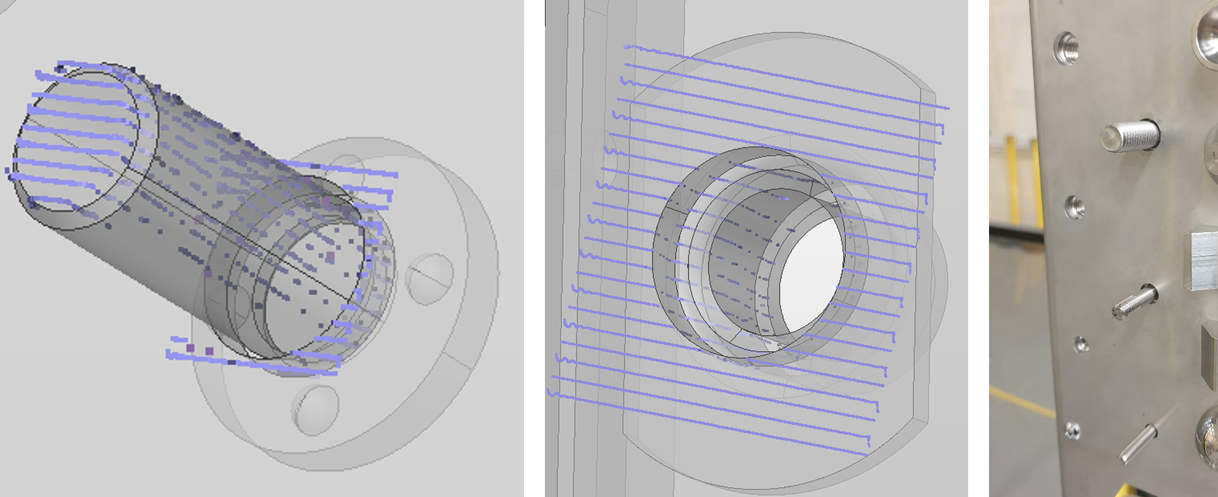
From the images above, the scan data clearly shows the extent to which the Laser Radar can capture data of the full length of the stud and inside the threaded hole from a single position.
The results of the measurements are shown below and for both Studs and Threaded holes, the average range of the measured position across each of the 30 measurements is under 30µm, with maximum range under 100µm across the distances and angles shown. For all data sets the same settings were used for the measurement and feature extraction simplifying the setup.
| Feature type | Distance | Incident angle | Max range of measured position | Average range of measured position |
| Stud | 1-5m | 15-75° | 84µm | 21µm |
| Threaded Hole | 1-5m | 15-50° | 93µm | 26µm |
The threaded hole incident angle is limited by the size of the hole and depth of the thread but is still capable of measuring repeatably across a wide range of angles.
The ability of the Laser Radar to measure features repeatably from a wide range of angles and distances allows a large field of view and high feature coverage meaning minimal positions are required for a measurement even across a full car body.
The accuracy of the Nikon Laser Radar can be measured using an independent artefact, such as an Inora tetrahedron. The Laser Radar has an MPE comparable to HA CMMs, and the results of measuring an Inora are below.
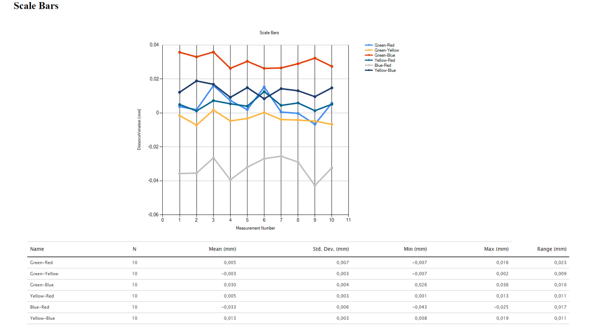
From the results above, we can see that the maximum deviation from the scale bar is 43µm.
These tests show the capability of the APDIS Laser Radar to measure these difficult threaded features directly and repeatably very quickly to global accuracy.
Being able to achieve repeatable, accurate data on the shop floor provides customers with trustworthy and actionable data to ensure build quality, reduce Work in Progress and increase First Time Through.
Request more information directly from our Sales and Application team in Europe here or check out our Resource Centre for Brochures and White Paper.
