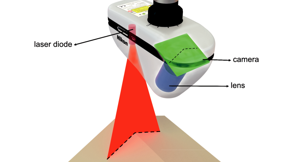
Laser scanners are remarkably efficient, flexible, and reliable measurement devices that can be combined with localizing technology in a variety of ways. Nikon Metrology, the subject of this paper, primarily focuses on laser scanners utilized on fixed coordinate measurement machines (CMM) or via hand-held models mounted to articulated arms. In either case, an optical scanner is used as the primary means of measurement, although the scanner is occasionally swapped out for a tactile probe in many cases for added capability. Scanners create interesting options for speed and accuracy, especially for applications involving complex and freeform parts. 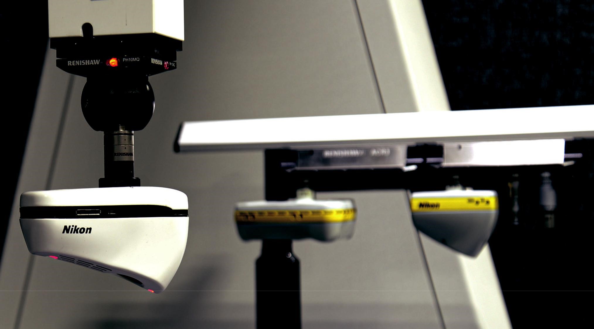 The technology that powers laser scanning relies on the emitting of light, which is then detected via the principle of triangulation, which was first developed in a working scanner by The National Research Council of Canada in 1978. 1 Triangulation uses the principles of geometry to determine the position of an object in space. The emitting light source, the laser line on the measured object’s surface, and a camera receiving the beam form a triangle. The distance and angle between the emitting light source and the receiving camera is known, as is the angle of the laser line on the surface. In simplified terms, Nikon Metrology laser scanners project the laser line onto the part. The camera then sees this image, which is converted into a series of dots based on the pixelation within the camera. The resulting calculation characterizes the measurement of the object under test. For a schematic of this process, please see figure 1.
APPLICATIONS & INDUSTRIES
No single measurement solution can measure 100 percent of all applications for all manufacturers. Fixed CMMs with tactile probes, generally set up in clean rooms separated from the production line, provide exquisite levels of accuracy and are easily automated, but cannot easily accommodate in-line inspection or very large parts. Portable, articulated arm devices with tactile probes can be taken to the part on the line and are superb at measuring parts with well-defined, prismatic shapes such as planes, circles, slots, spheres, however, they cannot efficiently handle freeform geometries like those found in turbine blades, which require very high resolution and even higher accuracies. Laser scanners, either localized on a CMM or a portable arm, work well with those freeform parts, most particularly those found in the automotive industry, but are somewhat limited in terms of measuring through very tight and narrow gaps. For this reason, in many cases manufacturers will utilize several complimentary technologies within their workflow, with scanners being an irreplaceable part of that equation. In fact, scanners and tactile probes are often interchanged on a CMM or an arm to achieve maximum measurement efficiency for complementary applications. A key point of discussion in world-class manufacturing facilities is the advent of Industry 4.0, which is shorthand for the web of automation that enables maximum speed and efficiency within the factory. The progression is toward a completely automated workflow with in-line inspection on the production line, offering feedback at any different point in time throughout the manufacturing process. This allows for not just an automated manufacturing process, but an adaptive one as well. The competitive pressures of the manufacturing industry mean hitting ever-tighter deadlines and achieving ever-better quality standards. As a natural consequence, scrap and returned items are severely curtailed and in some cases practically eliminated.
USE CASES: R&D AND PRODUCTION
To achieve these goals, manufacturers utilize laser scanning technology in two broad areas: research and development and production. Each have their own workflows and requirements. On the R&D side, the process generally is a matter of troubleshooting, of getting better insights into problems that might occur. A typical example would be in the automotive industry. The development of a car begins many months—sometimes years—before a prototype is even built, and laser scanners are integral to many steps in the process. Concept clay models are first built in the design studio. These go through multiple iterations, and scanners are used to record each and every one for detailed analysis. Initial fit studies in the pilot plant rely on parts being manufactured and precisely measured with scanners. And of course, tooling must be designed and implemented, which is another function perfectly suited to the strengths of laser scanners. The prototype is where all the parts of the car come together for the first time. Occasionally, some of those parts fail to align properly—the gaps are not where they should be, for instance. At that point, the quality team must investigate which specific part has been manufactured incorrectly. A laser scanner can quickly digitize all the different parts that are built together and provide easy-to-interpret insights via a color map, which includes a representation of the part in question. This is known as a “digital twin,” a virtual copy of the part with colors that indicate the deviation from the intended design. For example, an automobile can be considered as an assembly of detail parts; to determine fit, the user would scan each individual detail as a separate part. From there, the user can mount these virtual details to create the assembly, which includes locating the mating parts which must be carefully aligned. If a part contains three bolt holes and the user executes a virtual fit based on those three bolt-hole surfaces, the mating parts may interfere virtually. Thus, physically, they wouldn’t be able to be assembled without distorting something in a different area. Scanning enables virtual fits and exposes potential interference problems—perhaps a detail part was manufactured incorrectly, but the user will not know which part is wrong until they are virtually fit together. This process can be particularly useful in communicating to management the status of any necessary rework to the prototype. Again, the intuitive nature of the color scan/digital twin allows the deviations to be seen very clearly, even to someone who may not have a particularly deep technical background. Thus, laser scanning is extremely useful during the prototyping/R&D process, wherein laser scanners are used frequently to investigate and solve specific assembly problems. Users wishing to do this type of troubleshooting with a tactile probe might need to measure hundreds, thousands, or even millions of points to find the problem. A laser scanner, on the other hand, measures hundreds of thousands of points per second, so the technology provides far more data and much better insight to help diagnose and solve problems much faster. When utilized for production applications, in which everything is (theoretically at least) running smoothly and the initial problems have been ironed out, laser scanning provides the ability to sample parts and perform trend analyses. This is useful for members of the operations team in tracking and executing expected retooling of the part or parts being inspected. Once again considering the automotive industry, a manufacturer would typically have inspection programs created for every critical component that they are manufacturing. These are dedicated routines that they can quickly run to control the manufacturing process. They would take a part out of production, put it on the laser scanning CMM, load up one of the measurement programs for that part, and then let it run completely autonomously. Shortly thereafter, a measurement report is available that reveals if there are any deviations on that part; in addition, the program is usually linked with a database on which all historical data is stored. In addition to the pace at which information can be acquired with a laser scanner, it is faster than a tactile probe, meaning Laser Scanning the quantity of the information that can be provided in that same amount of time is generally higher. As an example, a user might wish to measure a piece of sheet metal by taking touch points on the surface to check the deviation on those locations. If that user currently measures 20 points, each one of those points requires a certain amount of time to move the machine and take a tactile touch point. If the number of points were to be doubled, of course it would take twice as much time to acquire that data. With the laser scanner, on the other hand, whether inspecting 20 locations, or 40, or 100, once the scan is taken covering the surface, all the inspection points are acquired at once. Therefore, increased information can be provided without increasing the cycle time. In this way, a laser scanner is generally faster and provides more information than a tactile probe. Over the different runs, production trends are revealed and technicians can predict when a specific location of a hole, let’s say, is slightly shifting. Based on that trending information, the teams can accurately predict when that feature will go out of tolerance and when it might be necessary to adapt the tools to correctly manufacture that hole. Production applications go beyond sampling, however. Depending on the type of product being built, 100% inspection may be necessary. For example, if the manufacturer is building something that simply cannot have defects, such as a medical device that will go inside someone’s body, that calls for 100% inspection. In the aerospace industry, tolerances are generally tighter than in automotive, and the critical importance of the parts being manufactured often demands 100% inspection as well. Traceability is a key deliverable of laser scanning, too. In the case of a critical failure, a supplier will want to have traceable measurement reports that demonstrate the issue did not stem from their components.
COMPARING AND CONTRASTING SOLUTIONS
To provide context and insight into laser scanning technology, we’ll focus on several discrete scanners from Nikon Metrology that address different sections of the market, starting with fixed CMM scanners. Each has different features enabling them to provide optimal measurement within specific applications and environments. A common feature amongst this line is their ability to measure difficult materials. Again, consider that scanners work with a laser that is projected onto the part and then viewed by a camera. If you have very shiny surfaces, it can be quite difficult (due to reflection) to accurately measure a feature. All scanner manufacturers claim to be able to scan shiny surfaces—and most can. But measuring shiny surfaces to collect data and measuring them to collect coherent and accurate data are two very different matters. The key advantage for Nikon Metrology scanners is that the laser intensity is optimized for every single point, allowing parts with very different material properties to be measured in a single scan. Other scanners may need to scan more than once at different settings to capture the same level of data—and even then, the acquired data may be noisy or sparse due to not being optimized “on the fly.” Nikon Metrology scanners offer a patented combination of hardware and software backed up with many years of experience and refinement. And the advantage comes not just in measuring shiny surfaces—shiny, matte black, and near-transparent surfaces can all be scanned in the same measurement. This leads to huge productivity gains. By not needing to adapt settings manually and/or perform redundant scans, Laser Scanning considerable time is saved. Further to this all important issue of productivity, Nikon’s real-time optimization of the laser settings is independent of the scanner speed. Other scanner technologies generally need to reduce the scanner speed to allow a higher dynamic range of the sensor, which negatively affects productivity.
The L100 is Nikon Metrology’s premium CMM scanner, and it has popular appeal within industry due to its superior combination of speed and accuracy. Users generally are looking for increased manufacturing efficiency as well as measurement performance in the same general area of tactile probes, and the L100 is the best scanner in the line for that scenario. The L100 is equipped with a high-quality, custom-designed glass Nikon lens that is optimized for laser scanning. This lens, in addition to the high-definition camera capable of capturing 2,000 non-interpolated points per line, results in a point resolution of 42 microns that enables the measurement of fine detail and sharp edges. In addition, the L100 has an exceptionally small probing dispersion value (according to the ISO10360-8 standard) of 26 microns, which is a measure of the scanner’s noise level, resulting in smooth meshes and high levels of detail. The measurement stripe width (i.e., the length of the laser line) of 100mm offer the ability to accurately capture a relatively large field of view, making the L100 very well suited to measure larger parts. Typical use cases would be within aerospace and especially the automotive industry. For example, any sheet metal part that goes into a car can be inspected in a quite robust way with the L100. This scanner can also quickly and efficiently measure a complete chassis as well as the smaller individual automotive components and assemblies. The L100 is the fastest of all Nikon scanners, meaning it can capture the most amount of data in the shortest time: 536 lines per second, and 420,000 points per second.
The LC15Dx scanner is Nikon Metrology’s most accurate laser scanner, down to 10 microns or less. The scanner is mainly used for applications requiring very high detail, often with smaller parts; the field of view is 15 mm wide. That tight field of view is what drives the high accuracy, providing exceptional resolution and yielding lot of points in a small area. This CMM scanner can be used to inspect parts demanding rigid tolerance, such as implantable medical devices, gears, or small turbine blades used in a jet engine. These blades typically have various characteristics and shapes that need to strictly comply with the design, especially with regard to the aerodynamics of leading and trailing edge of those blades. The cooling holes on these blades are quite small, making them difficult to measure with traditional tactile probes, which cannot access the tiny holes. These blades are freeform surfaces, which presents a multitude of problems for tactile probe. This is where an optical instrument such as the LC15Dx really shines. The XC65Dx, commonly referred to as the “cross scanner,” is a single scanner with three lasers and three cameras that form a three-laser cross in the middle, allowing measurements to be taken in almost any direction. This results in increased productivity, because the shortest amount of time for using a CMM scanner comes from the measuring; it takes far longer to move the CMM around and rotate the probe head to different orientations. The cross scanner takes that away by being able to measure in different directions at the same time from a single pose. The three cameras also enable the operator to move over a hole, sphere, slot, or edge in any direction and capture it. The cross scanner excels as a feature-measurement device integrated on large horizontal-arm, twin-column CMMs for near-line production in the automotive industry as a generic replacement for touch probes. Finally, these scanners can integrate with several different types of existing fixed CMMs. As should be clear, swapping out a laser scanner for a tactile probe on a CMM can provide a significant productivity boost, again, depending on the specific application.
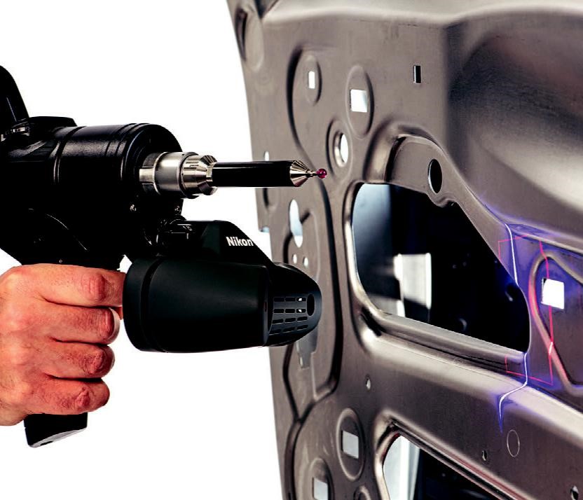
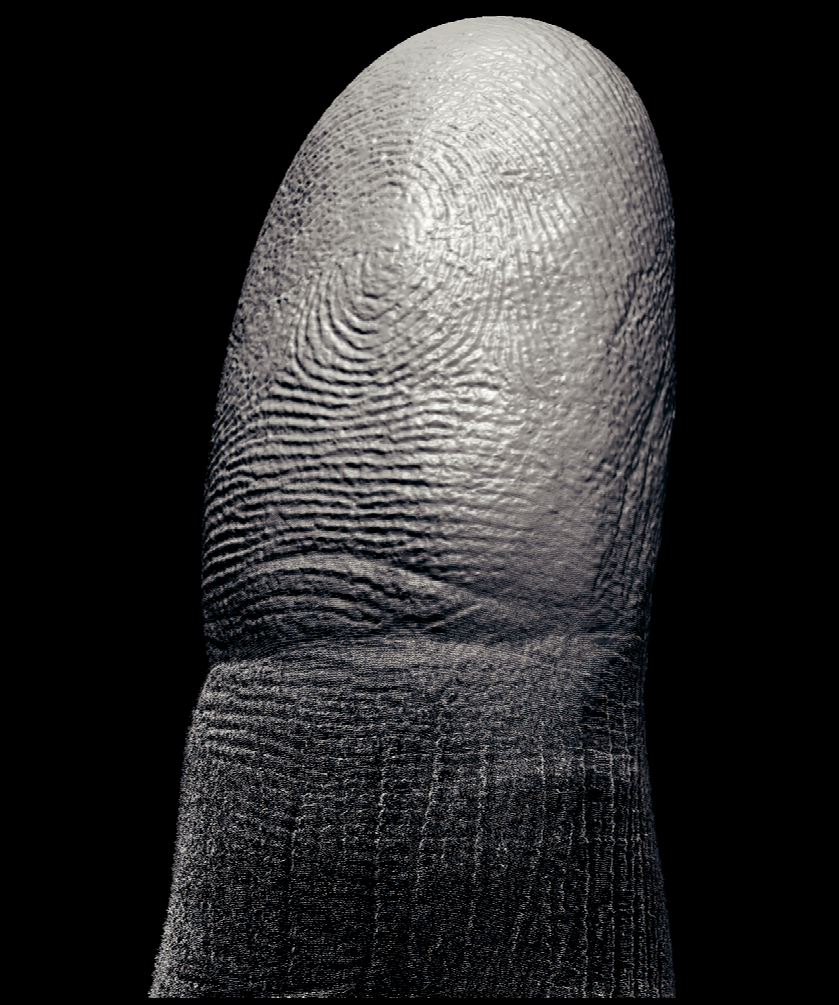
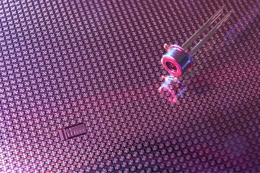
Turning to hand-held scanners, the ModelMaker H120 offers ultra-fast high-definition 3D scanning. It represents the latest piece of scanning technology in this line, providing exceptionally clean, clear, and sharp data. For some perspective on the kind of detail that the ModelMaker H120 can offer, please see figure 2. A user measuring sheet metal parts would not be scanning fingerprints, of course, but this image perfectly demonstrates the type of resolution levels that are possible with this scanner. Because time is money on the shop floor, a notable feature of the ModelMaker H120 is that it is a fully temperature-compensated scanner. Because of this, the system is ready to measure accurately in as little as four seconds, which eliminates productivity-killing warm-up time. Further adding to its utility and ability to positively affect throughput, the ModelMaker H120 can collect up to 450,000 points per second. In terms of measurement specs, the ModelMaker H120 offers a robust 120 mm field of view and an accuracy of 7 microns for the sensor only and 41 microns for the sensor plus the optimal articulated arm. The ModelMaker H120 is typically mounted to the MCAx S manual coordinate measuring arm, a seven-axis device that is available in half-meter increments, from 2 meters up to 4.5 meters in diameter. Together, the ModelMaker H120 and the MCAx S can be considered as a portable CMM. The hand-held scanner is incapable of fully automated inspection, but otherwise it is an exceptional solution for many R&D and in-line production applications.
SOFTWARE INTERFACES
Laser scanner systems like those discussed in the prior section integrate seamlessly across a wide range of software systems in addition to their own proprietary software, which not only analyzes the data collected from the scanners, but are also capable of programming the measurement of parts as well. In short, the software drives the hardware for data collection as well as analysis. Integration with third-party software is absolutely necessary because major automotive and aerospace manufacturers almost always standardize on a certain metrology software. The reason is to get the most consistent results by always using the same software with the same inspection routines and algorithms. There’s also consistency in terms of reporting; the operator can always get the same (or, at least, similar) reports, and the familiarity leads to great ease of use for the client. Given that backdrop, when companies like Nikon Metrology sell laser scanning systems, the clients typically already have a software that they like to handle their metrology work. As such, being able to integrate with all important software packages on the market is imperative. Nikon engineers have therefore developed an application programming interface (API) to work with various software vendors and maximize the quality of the scanning process, regardless of what software that client is working with. Although laser scanning software is usually found in R&D or production applications, there is another use that is important for a certain class of clients: reverse engineering. This tends to be found within product design, particularly automotive design, where the client has a design studio with clay models and 3D printers, as well as a high turnover of parts that they need to turn into CAD models relatively quickly. Many reverse- engineering workflows have tended to migrate more to clients in nations with emerging economies, such as India, Brazil, and China. Nikon Metrology does not have its own reverse-engineering software, but their scanners can directly interface with/scan directly in a variety of third-party reverse-engineering packages. Certainly, reverse engineering is an important segment of the market, but curiously, some users believe that the process does not need to be very accurate, so you can therefore have a worse scanner. However, in reverse engineering, you need an extremely good understanding of the shape of the part, with no fuzziness in the data, no noise, and absolute clarity. During inspection, a laser scanner will deliver a right or wrong answer—with a tolerance on something that is either inside or outside that tolerance. With reverse engineering, the tolerance is set by the user, who has to interpret the data and create CAD surfaces on top of that data, and it’s totally his or her interpretation as to the shape of the surface used to capture that data, whether it’s a plane or it’s something close to a plane or it’s a conic surface—and then there needs to be an understanding of how those surfaces blend together. It is something of an art form, which is why reverse engineering tends to stay a little closer to the service-oriented, more specialized end of the market. As parts get easier to manufacture and as production moves to 3D printing, the need to reverse-engineer parts will likely be less prevalent. However, every single item that is ever made will need to be inspected, forever, and the tolerances will continue to grow tighter.
NIKON DELIVERS BEST-IN-CLASS FOR THE FUTURE OF MANUFACTURING
Laser scanning is a powerful, flexible industrial solution that has a lengthy past and a bright future. Whether the scanners are mounted to a fixed CMM or a portable articulated arm, used for research and development or inspection on the production line, or analyzing data using its own software or third-party options, this is a technology offering a wide range of solutions to industry. Scanners are excellent measurement tools for freeform parts like turbines blades. On the other hand, tactile probes have significant limitation in dealing with these parts in terms of ease of use, speed of data acquisition, and overall cost effectiveness. Users within the automotive industry often consider laser scanning as the solution of choice for their most challenging applications. The phrase “time is money” is well worn, but it clearly applies to manufacturing in the Industry 4.0 world. Throughput is critical, and the pressures on efficiency will only increase in the years to come. For many applications, as demonstrated in this paper, laser scanning can save time while maintaining and even increasing accuracy. The results in terms of not only speed but the reduction of waste and rework are unambiguous. Moving forward, it is anticipated that laser scanning will continue to gain in market share. As recent technological developments from best-in-class scanner manufacturers like Nikon Metrology have demonstrated, the evolution of this technology will continue in response to competitive pressures and industry requirements. The result will be a continually improving set of technologies that will allow customer to manufacture better and more accurate parts more quickly, efficiently, and cost-effectively than ever before.


