In recent years, car manufacturers have been paying more attention to perceived quality, including how customers judge their vehicles’ overall build quality.
This is typically focused on how well the panels fit together, particularly the gap and flush between these panels. The gap between the front door and rear door is crucial not only for aesthetic reasons but also for functional reasons. A misalignment, such as the rear door being outboard of the front door, can lead to undesirable wind noise in the cabin, significantly impacting customer satisfaction.
To ensure the correct fitment of the panels in trim and final, the body in white (BIW) must be assembled correctly in the body shop. This starts with the tooling, where sub-assembly parts are pinned and clamped. As these smaller parts are assembled into an underbody and eventually a BIW, the build quality of these larger assemblies will directly affect the fit and finish (perceived quality) of the finished car.
The holes and surfaces that the tooling pins and clamping surfaces use are critical to achieve the build quality and ultimately perceived quality. Having accurate and precise data for these features is integral to ensure the tooling is correct, and ultimately the build quality of the BIW as this has direct influence on the fit and finish.
Many automotive body shops use inline measurement to measure the underbody and BIW assemblies. However, most of the technology used for this measurement is relative data – it is not absolute accurate. The data from relative systems, while useful, cannot be solely relied upon to determine tooling accuracy. When a relative system flags an issue (out of tolerance feature), it is crucial that the assembly is taken to a reference measurement system (CMM) to confirm or deny the results of the inline measurement system, ensuring accuracy and quality.
By using an absolute, traceable, accurate measurement system for measuring these assemblies in the body shop, the data can be used to adjust tooling to ensure improved build quality and give an accurate statistical analysis of the process because the data is absolute.
The Nikon Laser Radar can achieve CMM-level accuracy and repeatability on the shop floor, providing accurate, traceable, and trustable data, allowing automotive manufacturers to improve the process and quality of the assemblies at the point of manufacture.
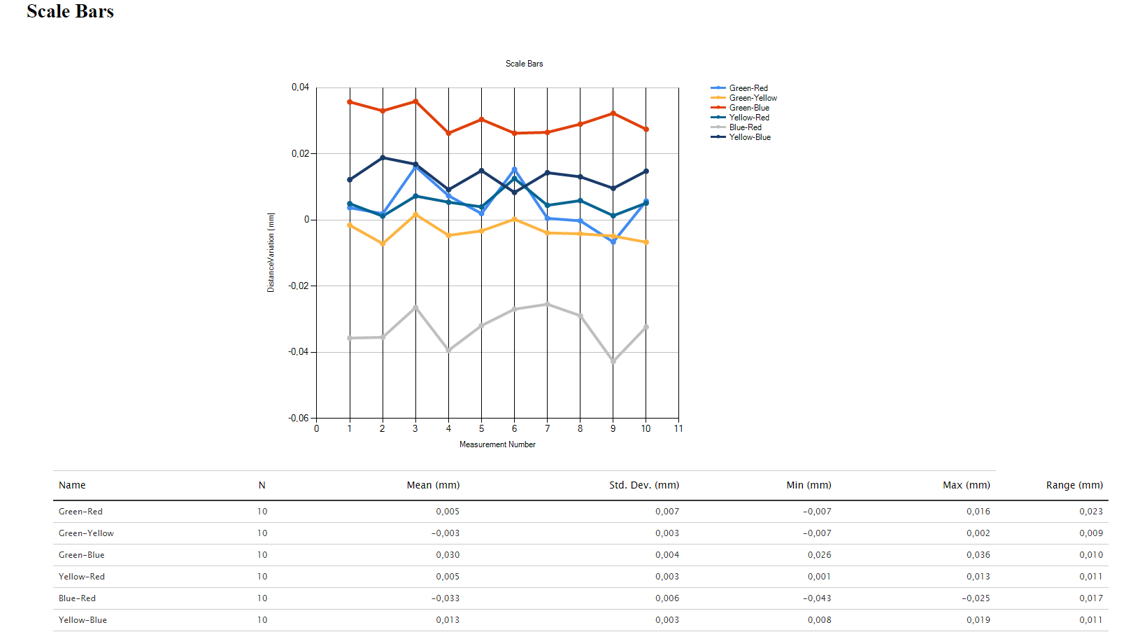
The accuracy of the Nikon Laser Radar can be illustrated using an independent artifact, such as an Inora tetrahedron. The Laser Radar has an MPE comparable to HA CMMs, and examples of the results of measuring an Inora are below.
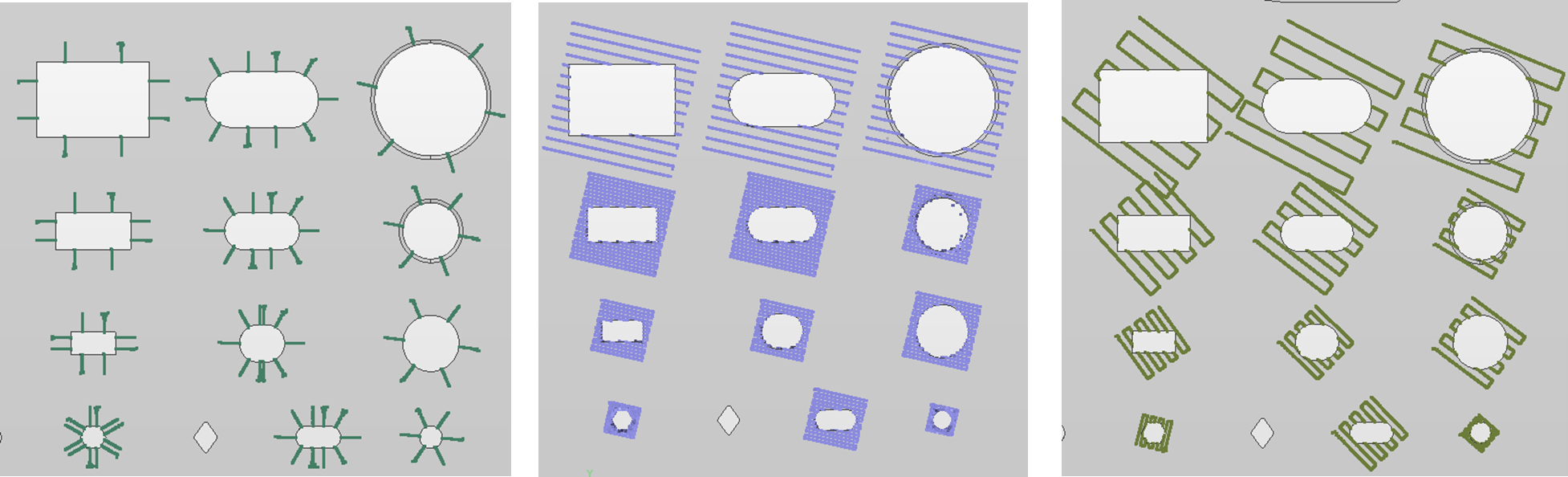
When measuring parts and components, the Nikon Laser Radar an infrared laser beam to capture scan data in specific patterns that is aligned to the CAD model. When measuring holes, rectangles, polygons, surfaces and slots the Nikon Laser Radar is able to scan the surface and edges of the feature and then extract the correct result compared to the CAD model.
The image below shows various scanning patterns for the Laser Radar to measure these key features.
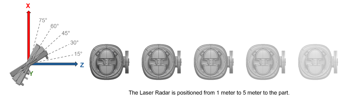
Recently, Nikon completed several tests for just these features on a test part. The Laser Radar measured each feature 30 times from several different ranges and angles to demonstrate the high repeatability achievable. These measurements were taken between 1 metre and 5 metres and up to a 75-degree incident angle.
Below is the illustration of the setup with the Laser Radar at five different ranges of the measured part.
The table below shows the maximum and average range of the measured position for each feature type across all distances and angles for the fast star pattern:
| Feature type | Hole | Slot | Rectangle | Polygon | Surface |
| Average Range | 0.05mm | 0.07mm | 0.06mm | 0,04mm | 0.02mm |
| Max Range | 0.10mm | 0.15mm | 0.16mm | 0.12mm | 0.05mm |
| Time to Measure | 2.6sec | 2.6sec | 2.3sec | 2.7sec | <0.5sec |
The range repeatability on these features is less than 160 microns, with an average range of less than 0.1mm for 30 measurements up to 60 degrees and from 1m to 5m for the star scan pattern and common extraction parameters.
If a more detailed scan pattern is used, such as those shown above, then the range can be reduced to under 0.12mm. However, it does take more time to measure, but it also allows for measurements at higher incident angles. This data illustrates how the Laser Radar is intolerant to angle and range configurations.
The Laser Radar’s practicality in measuring features repeatably from a wide range of angles and distances, providing a large field of view and high feature coverage, ensures minimal positions are required for a measurement even across a full car body.
The Laser Radar’s ability to achieve repeatable, accurate data on the shop floor instills confidence in the trustworthiness and actionable nature of the data, enabling automotive manufacturers to improve and validate the quality of the assemblies at the point of manufacture in the body shop.
With Nikon Laser Radar’s accuracy and repeatability, we can bring the CMM to the shop floor, ensuring quality, accurate, and repeatable data.
Request more information directly from our Sales and Application team in Europe here or check out our Resource Centre for Brochures and White Paper.
