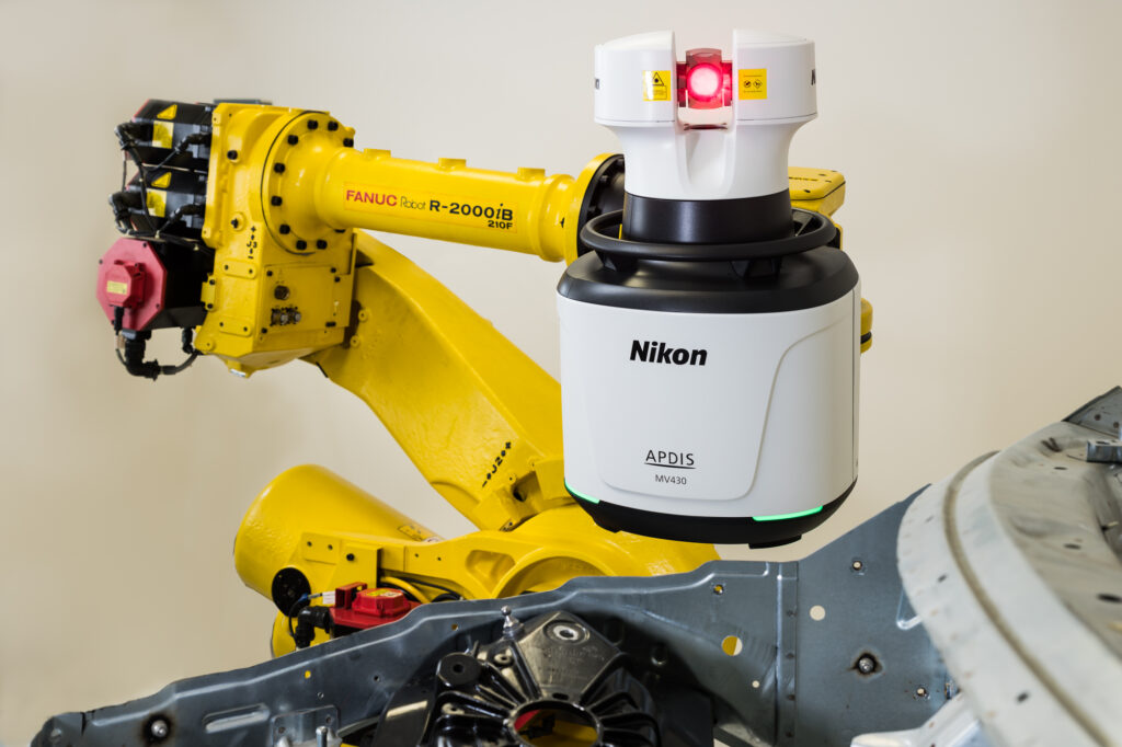
Thank you all very much for joining the first webinar session focusing on APDIS: Nikon‘s Laser Radar as a versatile plug and play multitool for agile and lean shop floor production. Watch the recording here:
With the growing challenges for lean and agile automotive production, reduction of lead times and ever-changing customer demands leading to fluctuating forecasting, trusted metrology processes have never been more important. To gather and use trusted data the goal should evolve around faster launches facilitated by faster learning curves and faster adaptations.
The APDIS Laser Radar can facilitate to achieve an agile and lean shopfloor production with the advantage to synchronize all measurement results from all applications, which creates a versatile working manner for the shopfloor engineers. All this supports non-silo measurement and working techniques and creates a common language on the shopfloor.
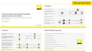
Dive into the world of overcoming silo measurement techniques with the APDIS Laser Radar and listen to the webinar here:
Find some frequently asked questions from this session here:
1. Which metrology softwares are available to be use?
APDIS can be used with Polyworks, Metrolog and Spatial Analyzer.
2. How do you prepare the object with the reference balls?
During the installation and commissioning phase of the project, the fixture/tooling will be measured with the APDIS unit to create an alignment (based on tooling certification data provided by the customer). Once an alignment is created from the tooling, the spheres (tooling balls) will then be measured from this alignment.
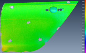
3. It’s possible to scan a surface with the Laser-Radar to create a color map?
Yes. We can either use a grid of points or line scans to create a color map.
4. Do you need the coordinates of the reference ball centers? How do you get these coordinates?
During the installation and commissioning phase of the project, the fixture/tooling will be measured with the APDIS unit to create an alignment (based on tooling certification data provided by the customer). Once an alignment is created from the tooling, the tooling balls will then be measured from this alignment.
The nominals (measured in the setup phase) of the tooling balls are at the center of the sphere. This allows for measurement (scan) the tooling ball from any direction, while always arriving at the same result – the center of the sphere.
5. What is the time to calibrate the system with the tooling balls per robot position?
This can be between 12 to 18 seconds, depending on the number of tooling balls required.
 Overcoming silo measurement techniques: absolute results over methods)