Established in 1984, Neuchatel-based Centre Suisse d’Electronique et de Microtechnique (CSEM – www.csem.ch) is now one of Switzerland’s top, globally recognised research and development institutes, specialising in precision manufacturing, advanced microelectronics, microtechnology and digitalization.
It is a private, not-for-profit organisation that designs, produces, assembles and tests novel products as well as solutions for their manufacture for companies in areas as diverse as health, agriculture, energy, aerospace, automotive, electronics and machine tools, while also supporting a strong local watchmaking industry that was instrumental in CSEM’s inception.
More than 400 experts are employed, one of whom, Lionel Kiener, was having trouble verifying the accuracy of components additively manufactured (AM) from a wide range of metals including stainless steel, titanium alloy, aluminium, bronze and copper using the layer-by-layer, powder bed, laser fusion method.
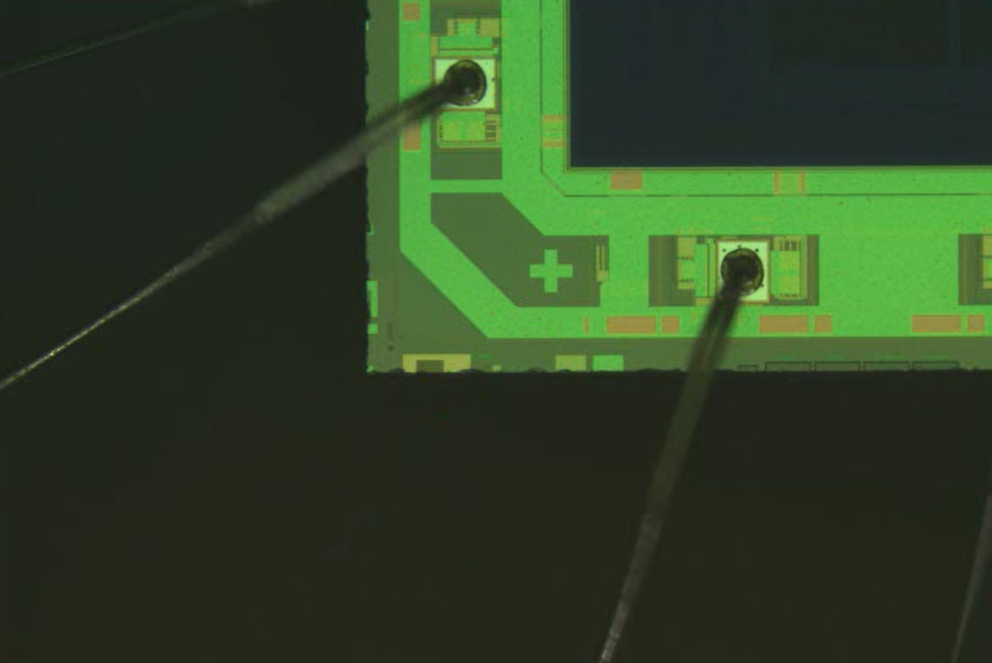
Using 2D optical metrology methods, it was challenging to inspect the accuracy of freeform surfaces of components in 3D space. Ascertaining how much distortion had been introduced as a result of heat input from the laser to the structure being built and predicting the exact shape of future components was nearly impossible. It was a particular problem in respect of compliant mechanisms that rely for their functioning on flexibility provided by elastic deformation of the constituent parts, as the final 3D geometry and dimensions have to be within drawing tolerance or their operation is compromised.
Mr Kiener commented, “Using our previous 2D measuring system was problematic, as we had no idea if the 3D shapes were meeting the design tolerances. So the overall precision of components could not be assessed and neither could the reproducibility between batches or even from one part to the next.”
To gain this metrology knowledge for complex 3D parts, CSEM needed to be able to measure surface shape to a reasonable accuracy. Nikon Metrology (www. nikonmetrology.com) advised that this could be achieved using its ModelMaker H120 non-contact laser scanner mounted on a 7-axis MCAx articulated arm. Several demonstration parts were sent to the supplier to verify that this could be done, after which the equipment was purchased together with Focus Inspection software to compare point cloud data collected from each scan to the nominal CAD model of the AM part or to the build process simulation.
Focus Inspection can easily be set up to automatically execute alignment, filtering and meshing as well as analysis and reporting. The software allows manufacturing information to be read directly from the CAD file, so features can be retrieved from the point cloud and their tolerances evaluated, eliminating error-prone and time-consuming manual entry of dimensions and tolerances. Creation of inspection programs by the teach-in method does not require any special skills.
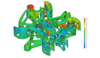
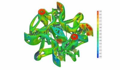
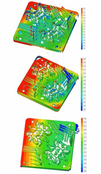
Scans of a pair of the mechanisms produced in the same powder bed build process. The surface variation from the CAD model and between the two is highlighted by the colour-coded images.
Mr Kiener continued, “We decided to opt for the Nikon Metrology solution due to the good quality of the results. The scanner’s point resolution down to 35 μm was precise enough for most of our applications involving additively manufactured parts. If we need higher precision, other methods such as interferometers can be used.
“Moreover, with its high frame rate and automatically optimised laser intensity at every point in each scan line, the ModelMaker H120 is even able to measure shiny, polished parts without the need for time-consuming surface preparation.”
The ability to accurately quantify distortions introduced during AM, as well as by thermal treatment and following any subsequent metal cutting, provides an end-to-end, digitised metrology solution that validates the accuracy of CSEM’s components. Additionally, it allows comparison of several parts in a batch and the averaging of out-of-tolerance results so that offsets may be fed back to the AM machine control to improve the manufacturing process. This in turn enables the performance of the final compliant mechanisms to be enhanced and their operational lifetime prolonged.
According to Mr Kiener, the training provided by Nikon Metrology in the use of the new inspection equipment was comprehensive and very helpful, which he regards as essential to extract the most from the system and especially the powerful software. He and his team were proficient in the use of the equipment within a couple of days of starting to use it.
He also said that the laser scanner has a field-of-view width of up to 120 mm for fast, detailed data collection over a large area at 2,000 points per scan line, so bigger mechanisms can be inspected. Components currently inspected span up to 1.5 metres, although the size, reach and freedom-of-movement of the MCAx arm will allow even more sizeable parts to be measured. In contrast, the previous optical 2D quality control equipment was unable to tackle anywhere near such large-scale work.
A further benefit to CSEM is that colleagues from other departments in Neuchatel also use the laser scanner to test the alignment and measure the precision of their systems.
